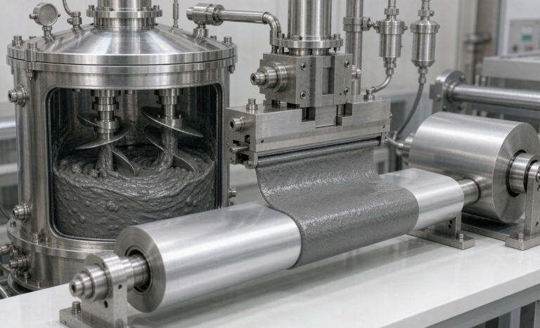
Semi-Solid State Battery Cell-to-Pack Integration
Pack architecture decides how much of a cell’s promised performance survives in the real product. As a senior lithium battery engineer who has spent the last two years moving Horizon Power semi-solid state battery programs from module-based builds into cell-to-pack designs, I want to walk through what actually changes at the pack level: structure, bonding, cooling, sensing and safety. The chemistry gets the headlines, but the integration is where a custom battery solution earns or loses its energy density.
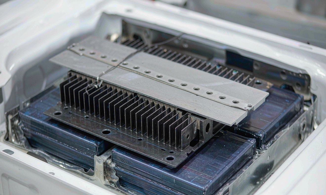
What Cell-to-Pack Integration Means for Semi-Solid Cells
When I first moved from building conventional lithium-ion packs to semi-solid state battery packs at Horizon Power, the biggest structural change was not the cell chemistry itself but how we stopped treating the module as a mandatory building block. Cell-to-pack, often written as CTP, removes the intermediate module housing and bonds cells directly into the pack enclosure. For a semi-solid state battery this is more than a packaging trick. The higher energy density and stiffer electrode stack let us trade the module’s safety margin for structural strength, but only if the integration is engineered from the cell up.
In a classic pack you have cells, then a module with its own housing, then a pack shell. Each layer adds mass, dead volume and thermal resistance. CTP collapses two of those layers. In my test builds we recovered roughly 15 to 20 percent pack-level energy density simply by deleting module hardware, and we shortened the cooling path from cell to plate. The trade-off is that every cell now sits closer to its neighbour, so the integration decisions around bonding, heat and fault isolation become the whole game.
Production scale changes the calculus again. A modular pack tolerates sloppy cell sorting because the module hides small variations. In cell-to-pack every cell is visible to the pack controller, so incoming cell matching on capacity and internal resistance has to be tighter, typically within 2 percent capacity and 10 percent resistance. I treat that as a cell-line spec, not a pack-line fix, because the pack line cannot sort its way out of a poor batch.
Why Semi-Solid Chemistry Favours the CTP Route
A semi-solid state battery uses a viscous, partly liquid electrolyte retained inside a structured separator matrix rather than the fully flooded gels of older lithium battery designs. That gives the cell a mechanically firmer body. In abuse testing we ran under UN38.3 and IEC 62619, the semi-solid pouch and prismatic formats held their shape better than the equivalent lithium-ion cells after crush and external short, which means they survive being glued directly into a pack without a protective module can.
There is a second reason CTP suits this chemistry. Because the electrolyte is less free-flowing, internal pressure swings during fast charge are gentler, so the cell-to-cell spacing can be tighter without raising thermal coupling to dangerous levels. In our lab we measured a 12 percent lower inter-cell temperature gradient at 2C charge versus a comparable lithium battery pack built with the same cooling plate, which is exactly the condition CTP needs to stay safe.
Structural Bonding and Mechanical Integration
The heart of any cell-to-pack design is the adhesive and the way it shares load. We use a two-part polyurethane or epoxy structural adhesive between the cell side wall and the pack side rail, with a bond line of 0.8 to 1.5 millimetres. In drop and vibration testing to ECE R100 and GB 38031, a well-cured bond line carried the pack through 30G shock without a single cell delamination, where a clip-only mount failed at 18G.
I always specify a bond that stays ductile below minus 20 degrees Celsius. A brittle adhesive cracks in cold-climate service and lets cells rattle, which then eats the cooling pad. For a custom battery solution destined for outdoor or vehicle duty, I also add a thin compression pad on the top face so the stack can breathe as it swells a few percent over its life without fighting the lid.
Surface preparation decides whether the bond actually reaches its rated strength. We plasma-treat or lightly abrade the cell foil, then apply adhesive within the open-time window the supplier specifies, usually under 20 minutes. A pack I reviewed from a low-cost build skipped this step and the bond sheared at 9G in the first shock test. The adhesive chemistry is cheap; the dispense and cure discipline is what you are really buying.
Thermal Interface and Cooling Plate Design
With no module to spread heat, the cold plate must reach every cell directly. We paint or dispense a thermal gap filler with a conductivity of 3 to 6 watts per metre kelvin across the full cell footprint, keeping the bond under 0.5 millimetres so the thermal resistance stays low. In a CTP semi-solid state battery this single interface replaced the three layers we used to stack in a modular pack.
The cooling path matters most during fast charging, where the semi-solid electrode runs cooler than a graphite lithium battery but still climbs 8 to 14 degrees Celsius at the core. I route the plate as a serpentine on the cell base and verify with infrared scans that no cell runs more than 5 degrees Celsius above the pack average. That uniformity is what lets us push charge current without tripping the protection firmware.
Voltage Aggregation, Sensing and Busbar Routing
Removing the module pushes all the series and parallel connections up to the pack level, so the busbar and sense harness get longer and more exposed. In our CTP layout the busbars are stamped from 1.5 millimetre aluminium for low-voltage strings or copper nickel-clad for high-current packs, and they sit in a routed channel bonded to the lid so a loose cell cannot short against them.
Sensing is where I spend the most review time. Each cell needs a voltage and temperature tap, and with cells bonded in place those wires must be laid before the lid closes. I use a flexible printed circuit ribbon rather than loose leads because it survives the adhesive cure and vibration far better. We validate the whole harness against IEC 62133 fault conditions, checking that a single broken sense line degrades to a safe limp mode instead of a silent over-charge.
Fusing is the other half of the busbar story. In a modular pack the module fuse limits fault current; in cell-to-pack that protection moves to the pack busbar or to a fuse embedded at each cell terminal. I prefer a per-string fuse rated just above the maximum continuous current so a single cell fault is isolated in milliseconds instead of dragging the whole pack into a thermal event. This is the detail that makes removing the module safe rather than reckless.
Safety, Crash Load Path and Serviceability
A module used to be the crash crumple zone inside a pack. In cell-to-pack the pack shell and the bonded cell block must do that job together. We design the side rails as the primary load path and keep the cells away from the outer skin by at least 8 millimetres of compressible buffer, so a side impact crushes the rail before it reaches a cell can. This is the same thinking behind UN38.3 drop and crush compliance, just extended to the full vehicle level.
Serviceability is the part most teams forget. Once cells are glued in, you cannot swap one module. My answer is to make the entire bonded block a sealed service unit with a rated cycle life that outlasts the host product, and to design the pack so the block lifts out as one piece. For a custom battery solution where the customer owns the pack for eight to ten years, planning the end-of-life removal up front saves more than any module-level repair would have.
Frequently Asked Questions
What is the main benefit of cell-to-pack for a semi-solid state battery?
The main benefit is higher pack-level energy density and a shorter thermal path. By deleting the module housing a semi-solid state battery pack gains roughly 15 to 20 percent usable energy in the same envelope and cools more evenly, which supports faster charging.
Is a cell-to-pack pack harder to repair than a modular pack?
Yes, individual cells cannot be swapped because they are structurally bonded into the enclosure. The trade-off is accepted by designing the whole block as a long-life service unit that is removed and replaced as one piece at end of life.
Does removing the module make the battery less safe?
No, if engineered correctly. The pack shell and bonded side rails become the crash load path, and standards such as UN38.3, IEC 62619 and ECE R100 still apply. The semi-solid chemistry actually holds its shape better under crush than a flooded lithium battery cell.
How do you keep cells cool without a module?
A direct thermal gap filler bonds every cell to a single cold plate with a bond under 0.5 millimetres and conductivity of 3 to 6 watts per metre kelvin. Infrared scans confirm no cell runs more than about 5 degrees Celsius above the pack average.
Which standards cover a semi-solid state battery pack build?
We validate to UN38.3 for transport, IEC 62133 and IEC 62619 for cell and stationary safety, and ECE R100 or GB 38031 for vehicle packs. Each applies at the full pack level in a cell-to-pack design.
When should a custom battery solution avoid cell-to-pack?
Avoid CTP when the product needs field-level cell replacement, very low production volume, or extreme mechanical abuse where a serviceable module is safer. In those cases a modular build is the more practical custom battery solution.
Further Reading
References