Semi-Solid State Battery Current Collector Foil Selection
Every electrode in a lithium battery does two jobs: store lithium, and hand the electron to the outside circuit. The first job gets all the attention in cell design reviews. The second one is decided almost entirely by a sheet of metal 10 to 20 microns thick that most teams never question until a pilot line starts scrapping cells. I have spent years building semi-solid state battery cells, and I can tell you that current collector foil selection is one of the quiet decisions that separates a cell that ships from a cell that fails on the cycler.
Why Foil Choice Matters More in a Semi-Solid Cell
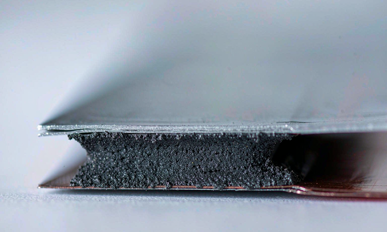
A conventional liquid-electrolyte cell spreads its active material in a thin, well-bonded coating that behaves almost like a rigid film. A semi-solid state battery works differently. Its electrode is a gel-like composite with a high active material loading, often 80 to 120 microns thick per side instead of the 60 microns we see on a standard electrode. That thicker layer stores more energy per unit area, which is the whole point, but it also moves. The electrode swells and contracts on every cycle, and the foil underneath has to absorb that motion without cracking the coating or losing electrical contact.
The foil is therefore not a passive conductor. It is the mechanical backbone of the electrode. If it is too soft, the coating delaminates after a few hundred cycles. If it is too brittle, it fractures at the edges during winding or stacking. If its surface is too smooth, the semi-solid layer never keys into it in the first place. In my experience, foil specification accounts for a surprising share of early cycle-life failures, and it is almost always cheaper to fix at the design stage than on the line.
Aluminum on the Cathode, Copper on the Anode
Chemistry sets the first rule, and it is not negotiable. The positive electrode operates at a high potential, typically 3.0 to 4.3 volts against lithium, where copper would oxidize and dissolve. Aluminum handles that window because it forms a thin, self-healing oxide layer that keeps the bulk metal stable. The negative electrode sits near zero volts, where aluminum would alloy with lithium and fall apart, so copper takes that side because it is stable against reduction at low potential.
For a semi-solid state battery, I work with a narrow set of practical grades:
- Cathode side: aluminum foil at 99.5 percent purity or better, typically grades 1060, 1070, or 1085, with a thickness of 12 to 16 microns.
- Anode side: copper foil at 99.9 percent purity, either rolled annealed or electrodeposited, with a thickness of 6 to 10 microns.
- Both sides: a bright, defect-free surface with controlled roughness rather than a mirror finish.
The cost gap is real. Copper trades at roughly three to four times the price of aluminum per kilogram, and because copper is also denser, it adds more mass per square meter. That is why anodes use the thinnest sound foil the process can handle, while cathodes can afford a little more metal. On a 20 kWh pack, the difference between a 6 micron and a 9 micron copper foil is measurable in both mass and dollars, and it is the kind of lever a good design team revisits every generation.
Thickness Trade-Offs: Mass, Resistance, and Yield
Thinner foil raises energy density because it removes dead metal that stores no lithium. That is the entire argument for going thin. The counter-argument is mechanical. As thickness drops, tensile strength and tear resistance fall with it, and the foil becomes harder to coat, dry, calender, and handle without wrinkling or pinholes.
The electrical trade-off runs the other way. Every micron of foil adds in-plane resistance and a little heat under high current. In a semi-solid cell with a thick coating, the current path through the electrode is already longer than in a thin-film cell, so I keep the foil resistance low enough that it does not dominate the internal resistance budget. My rule of thumb is to plot cell resistance against foil thickness and find the point where the curve flattens; beyond that point, saving another micron buys almost no energy density but starts costing yield.
There is a second-order effect that catches people out: thickness tolerance. A foil nominally 8 microns thick that varies by plus or minus 10 percent across the web will coat unevenly, and the resulting electrode will have soft spots that fail first. I specify tolerance as a percentage of nominal, not a fixed micron window, and I require the supplier certificate to state the measurement method.
Surface Treatment and Adhesion to a Semi-Solid Layer
A semi-solid electrode has less free binder than a conventional slurry, so it cannot rely on chemistry alone to hold onto the foil. Adhesion comes largely from mechanical interlock, which makes the foil surface a design variable rather than a commodity property. Three treatments show up in production:
- Corona or plasma treatment raises surface energy and improves wetting when the gel is applied.
- A thin carbon primer, usually one to two microns, adds a conductive tie layer that also blunts the mechanical mismatch between metal and electrode.
- A ceramic or boehmite coating on the cathode foil raises thermal stability and reduces the chance of a hard short at the edge.
Roughness is the common thread. I target a surface roughness of about 0.3 to 0.6 microns, measured as Ra, which gives the gel something to grip without creating peaks that puncture the separator. I verify adhesion with a peel test and look for 5 to 15 newtons per meter, then confirm it after formation and after a hundred cycles. A coating that passes at build but halves its peel strength after cycling is a delayed failure, and it shows up as capacity fade long after the foil decision was locked in.
Tab Welding, Edges, and the Current Path
The foil only matters if the current can leave the cell, and that happens at the tabs. In a semi-solid state battery, the electrode stack is often thicker than a conventional one, so the uncoated foil edges that get welded into the tab carry a heavier burden. Ultrasonic welding is the usual choice because it joins the stack without melting the metal, but it is unforgiving of thin, soft foil. Too little energy and the weld is cold and resistive; too much and the foil tears or the tab burns through.
I specify foil hardness and elongation with the weld in mind, not just the coating. A foil that coats beautifully but tears under the sonotrode is a process failure waiting to happen. I also keep the uncoated edge width consistent, because a ragged or narrow edge makes weld quality vary from cell to cell. If your weld schedule is being retuned every batch, the foil specification is often the hidden variable.
Corrosion, Supply, and What I Specify in Production
Two practical risks drive the final choice. The first is corrosion at high voltage. Modern high-nickel cathodes push the upper cutoff toward 4.3 volts and beyond, where a marginal aluminum foil can pit and dissolve if its oxide layer is imperfect. I test candidate foils with a hold at the top of charge and inspect for pitting before I approve them. The second risk is supply. Battery-grade aluminum and copper foil is a concentrated industry, and lead times can stretch when demand spikes, so I qualify at least two suppliers per side and keep a validated fallback.
When I hand a specification to the line, it is short and unambiguous: grade, purity, thickness and tolerance, roughness, surface treatment, tensile properties, and the test methods that prove each one. At Horizon Power, a custom battery solution starts with those inputs rather than ending with them, because the foil travels through every downstream process and quietly sets the ceiling on what the cell can do. Get it right at the start and the rest of the build has room to work. Get it wrong and no amount of clever cell design will recover the yield.
Frequently Asked Questions
What thickness of current collector foil should a semi-solid state battery use?
Most semi-solid state battery designs I work on use aluminum foil of 12 to 16 microns on the cathode and copper foil of 6 to 10 microns on the anode. The exact number depends on how thick your coating is and how much current the cell must carry. Thinner foil raises energy density but reduces mechanical strength and manufacturing yield, so the right value sits where the resistance curve flattens and the process stays stable.
Can I use the same foil grade as a conventional lithium battery?
You can start with the same base grades, but you should not assume the same specification will work. A semi-solid electrode is thicker and more compliant, so it demands better adhesion and more consistent surface roughness than a conventional slurry needs. I keep the alloy family, such as 1060 or 1070 aluminum, but tighten thickness tolerance and add a primer or surface treatment that a standard cell might not require.
Why does foil surface roughness matter so much?
Semi-solid electrodes hold on mainly through mechanical interlock, so roughness is how the gel grips the metal. Too smooth and the coating delaminates; too rough and the peaks can damage the separator. I aim for a roughness around 0.3 to 0.6 microns Ra and confirm it with a peel test after formation. Roughness is one of the few foil properties that directly predicts cycle life rather than just initial build quality.
Does foil choice affect fast charging?
Yes, indirectly but clearly. A thicker or more resistive foil adds to the internal resistance, which means more heat and a lower safe charging current. Because fast charging is often limited by heat rather than by the chemistry, trimming in-plane resistance through proper foil selection gives the cell more headroom to accept current. That said, the electrode thickness and tab design usually dominate, so foil is one input among several.
Does aluminum foil corrode in a semi-solid cathode?
It can, if the upper cutoff voltage is pushed too high or the foil quality is marginal. Aluminum survives because it forms a passivating oxide layer, but that layer is fragile at the top of charge with high-nickel chemistries. I qualify every cathode foil with a voltage hold test and inspect for pitting before approval, and I prefer a ceramic coating where the cell will routinely sit above 4.2 volts.
How does Horizon Power qualify a current collector foil for production?
We run a short, fixed sequence: baseline the foil grade, purity, thickness, and roughness against the certificate; coat a pilot batch; measure peel strength before and after formation; build a small cell lot for cycle testing; and confirm tab weld quality across the batch. Only foils that pass all of those gates reach volume. We also qualify a second supplier for each side so a single point of supply cannot stall the line.
Further Reading
References