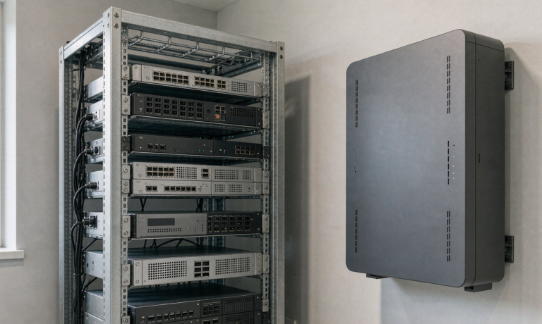
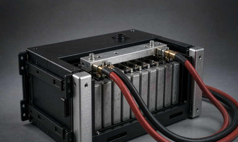
Home Energy Storage Rapid Shutdown and DC Disconnect
As a senior lithium battery engineer, I have commissioned dozens of residential storage systems across three continents. One question comes up in nearly every inspection: how do we make sure the DC side of a home energy storage system is safe for firefighters and service personnel? The answer sits in two code requirements that many installers still treat as optional. This article explains what a home energy storage rapid shutdown system must do, where the DC disconnect belongs, and how to size and label it so your installation passes the first time. I will also show the three field tests I run before I sign off, because that is where most jobs either clear or fail.
Why Rapid Shutdown Matters for Home Energy Storage
In a grid-tied home energy storage system the battery string can sit at 48 V, 96 V, or even 400 V DC. After an inverter shuts down, that voltage does not disappear. A firefighter cutting through a roof or wall can meet a live conductor that the AC side has no control over. Rapid shutdown was written into the National Electrical Code to remove that hazard within a defined time and distance from the array or battery enclosure. For home energy storage rapid shutdown, the rule from NEC Article 690.12 is that conductors more than 1 foot from the boundary of the storage system must be reduced to 30 V within 30 seconds of initiation. The 80 V touch-safe limit applies within 1 foot of the boundary. I have watched inspectors fail an otherwise perfect job because a single rooftop combiner was still reading 380 V ten minutes after the switch was thrown. The fix is never expensive. It is planning, and it starts at the design stage rather than the inspection stage.
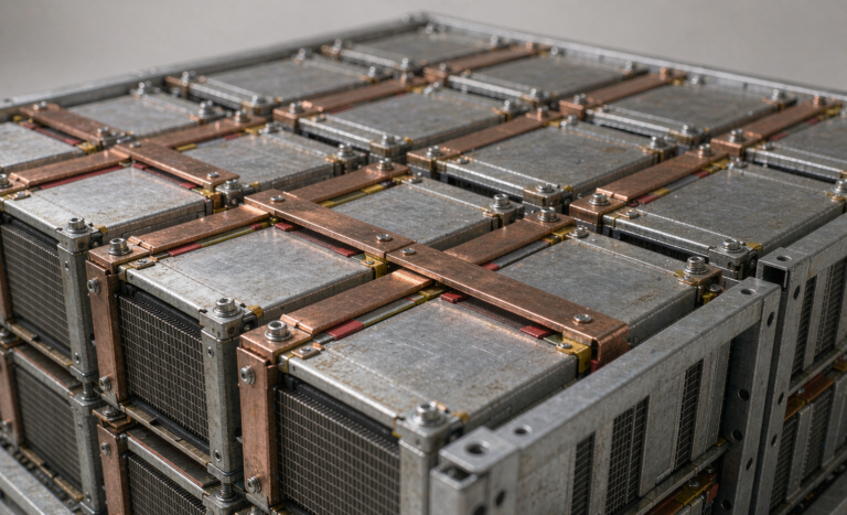
The hazard is not theoretical. A lithium battery pack holds energy whether or not the sun is shining or the grid is up. Unlike a photovoltaic module that stops producing when light is blocked, a storage string keeps its full open-circuit voltage available at the terminals until something physically opens the circuit. That is why rapid shutdown and the DC disconnect are two halves of the same safety story. One reduces voltage at a distance, the other gives a person a certain point to open.
Where the DC Disconnect Belongs
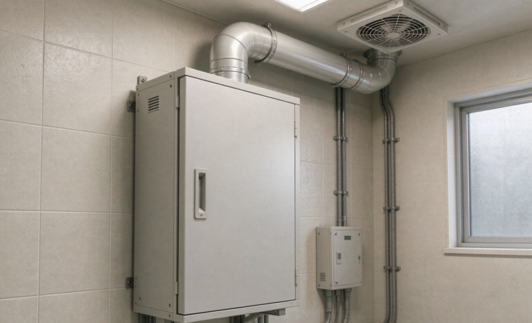
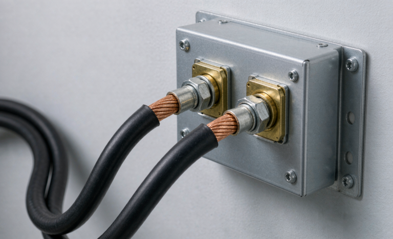
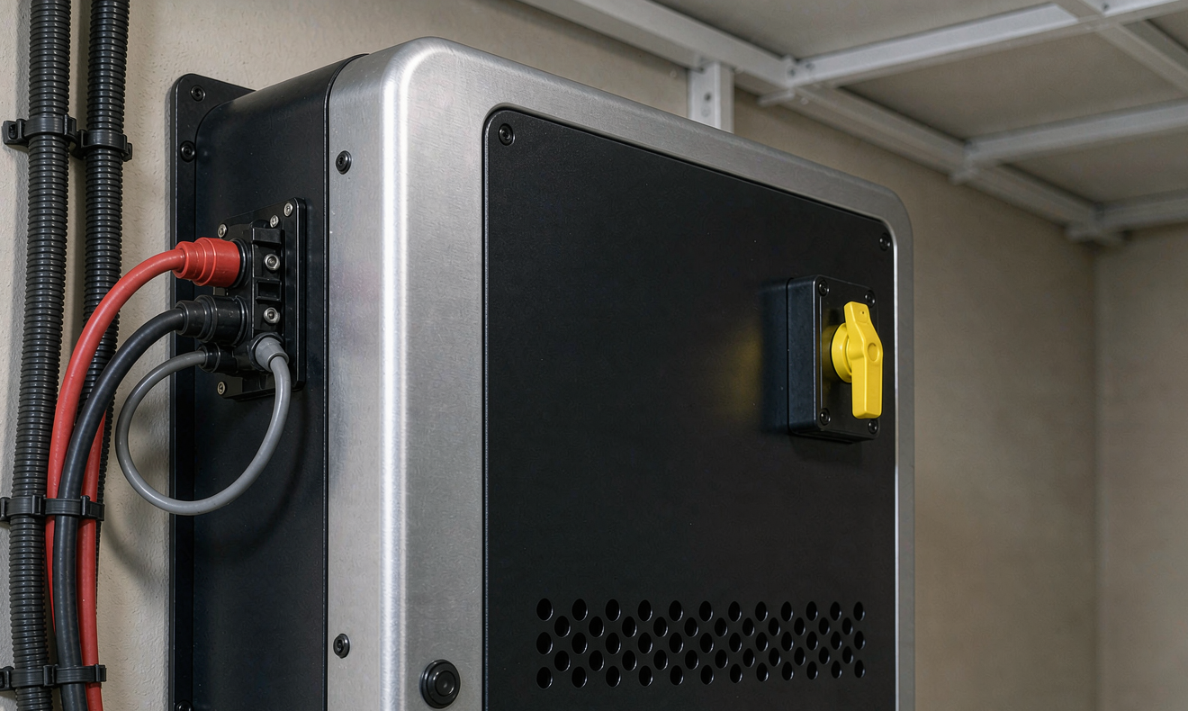
Every home energy storage battery bank needs a dedicated DC disconnect that is within sight of, or clearly identified for, the service personnel. I prefer a listed enclosed switch rated for the full short-circuit current of the string, mounted on the wall beside the inverter rather than buried inside it. The reason is simple: when something goes wrong at 2 a.m., you want one handle that opens the battery circuit with no ambiguity. Many consumer inverters have an internal DC switch, but code and good practice both call for an external, lockable disconnect. For a 48 V lithium battery pack the disconnect must break the full continuous rating plus any inrush from the BMS contactor. For a high-voltage 400 V home energy storage system the disconnect is part of the service entrance equipment and must meet the same interrupting rating as the inverter DC input. A custom battery solution that skips the external disconnect is, in my view, not a finished product.
Location also affects response time. I keep the disconnect within three steps of the inverter and never behind a locked door that a responder cannot open. If the battery sits in a garage or exterior enclosure, the disconnect goes on the same wall as the entry point so the circuit can be opened before anyone steps inside. This small detail has saved more time during drills than any label ever will.
Sizing the Disconnect and Overcurrent Protection
Sizing starts with the battery’s maximum continuous discharge current, not the inverter’s nameplate. I once reviewed a 10 kWh system where the inverter said 100 A but the lithium battery could deliver 180 A for 10 seconds during a motor startup. The disconnect and fuse must carry the continuous load and interrupt the fault. A common field mistake is to copy the AC breaker size onto the DC side. DC arcs are far harder to break than AC because the current does not pass through a natural zero crossing. That is why we use DC-rated switches, often with magnetic blowout, and pair them with class T or semiconductor fuses. As a rule I size the disconnect at 125 percent of the continuous current and verify the interrupting rating against the available fault current at the battery terminals. UL 1741 outlines the inverter interconnection requirements, and the disconnect is the physical layer that keeps those requirements honest.
Fuse coordination deserves its own sentence. The fuse must clear a short on the battery side faster than the conductor insulation is damaged, but it must not nuisance-trip during the normal inrush of a contactor closing. I set the fuse rating at roughly 1.5 times the continuous current and confirm the let-through energy stays inside the cable’s short-circuit rating. Skipping this step is the quiet cause of most field failures I am called to diagnose.
Coordinating the Disconnect with the BMS and Inverter
The disconnect is not an island. A well-designed home energy storage rapid shutdown path tells the battery management system to open its internal contactor at the same moment the external switch is thrown. I look for a system where the BMS senses the disconnect state and parks the cells in a safe, low-current condition rather than fighting the open contactor. If the inverter and BMS speak different shutdown languages, the conductor can stay energized longer than Article 690.12 allows. During commissioning I deliberately trigger the disconnect with the battery under load to confirm the BMS and inverter both report a clean isolation within the 30 second window. A battery system that passes this test once tends to pass it every time.
Labeling, Location, and Lockability
An unlabeled disconnect is a disconnect that does not count. The NEC requires a marking that identifies the equipment served and the voltage class, and the switch must be lockable in the open position. I keep a simple field checklist: yellow caution label, voltage and polarity, lockable handle, and a clear path to the battery without climbing over stored items. For home energy storage rapid shutdown the boundary markings matter too. The 1 foot and 3 foot boundaries from Article 690.12 must be marked so a responder knows where touch-safe limits apply. In cold climates I also confirm the enclosure is rated for the location, because a NEMA 3R box in a heated garage is different from one on an exterior wall at minus 25 degrees Celsius.
Commissioning Tests I Run Before Sign-Off
Before I hand a system to the homeowner, I run three checks. First, I initiate rapid shutdown from the specified control and measure the conductor voltage at the 1 foot boundary sixty seconds later; it must be below 30 V. Second, I open the DC disconnect and confirm the battery side reads open circuit on every pole. Third, I verify the BMS reports the string as isolated and that the inverter shows a clean DC loss-of-power fault rather than a cryptic error. I log these readings. When a future service call or inspection happens, that paper trail is the difference between a five-minute confirmation and a full teardown. For lithium battery systems I also confirm the cells stay within the UN38.3 and IEC 62133 envelope during the test, because a disconnect event that stresses the pack is worse than no disconnect at all. NFPA 855 spacing rules round out the picture by keeping the enclosure away from ignition sources.
Frequently Asked Questions
What voltage must rapid shutdown reach within 30 seconds?
For home energy storage rapid shutdown under NEC Article 690.12, conductors outside the 1 foot boundary must drop to 30 V or less within 30 seconds of activation. Within 1 foot of the boundary the limit is 80 V. These are measured open-circuit values on the conductor, not at the inverter terminals.
Can I use the inverter internal DC switch instead of an external disconnect?
Technically the inverter switch can isolate the unit, but most authorities require a separate, lockable, externally visible DC disconnect for the battery. It gives responders a single unambiguous point to open, and it survives a dead inverter. I always install the external switch.
Does rapid shutdown apply to off-grid home energy storage?
Yes. The safety concern is the same live DC bus, whether or not the system is grid-tied. Off-grid home energy storage still needs a disconnect and should follow the same 30 V within 30 seconds logic for any exposed conductors.
How do I size a DC disconnect for a 48 V lithium battery?
Take the battery’s maximum continuous discharge current, multiply by 1.25, and select a DC-rated switch with an interrupting rating above the available fault current at the terminals. Pair it with class T fuses sized just above the continuous load. Do not reuse the AC breaker size.
What label is required on a home energy storage disconnect?
The disconnect needs a permanent marking that names the served equipment, the voltage class, and a warning that live parts are present. It must be lockable in the open position, and the Article 690.12 boundaries should be marked so responders know where touch-safe limits begin.
Further Reading
References