Battery Solution for Electric Refuse Trucks: Route Duty
As a senior lithium battery engineer at Horizon Power, I have spent twelve years specifying traction packs for commercial vehicle builders, and the electric refuse truck is one of the hardest duties in my notebook. A collection route is not a long highway run. It is a stop start cycle with a hydraulic packer firing every two or three minutes, a battery pack replacing the diesel engine, and a driver who must finish the route by 14:00 whether the pack feels like it or not. In this article I show how we size an electric refuse truck battery solution from a real route duty profile, what thermal and mechanical protection an underbody mount needs, and how depot charging changes the pack design.
What a Refuse Route Demands from the Pack
Most chassis builders quote a pack size from a homologation range number, and that number is a poor guide here. A 26,000 to 34,000 pound (12 to 15 tonne) refuse cab usually carries 300 to 500 kilowatt hours, and a typical urban route consumes 250 to 350 kilowatt hours over eight to ten hours. The energy is only half the problem. The peak power is the part that sets the cell spec.
Every compaction cycle fires a hydraulic pump and a packer motor, and the current spike lasts a few seconds while the pack voltage sags. On a municipal program we audited in the Gulf region, the route drew 312 kilowatt hours in eight hours with 41 compaction events per hour. The pack peaked at 380 amperes at 540 volts, a four times per hour burst rate held for about six seconds at each stop, then dropped back to 40 to 70 amperes of steady driving current. That shape, high burst, long idle, repeated 300 to 500 times per shift, is what a refuse duty cycle really looks like on a bench.
This is why a refuse truck pack is designed for power bursts layered on top of a moderate energy baseline. If you copy a delivery van pack and put it under a packer, the cells see the same average current but far more charge transferred through them each shift, and the state of charge swings much wider.
Sizing the Pack for Route Energy, Not for Range
We start every electric refuse truck battery solution with a route energy audit. The driver log, the GPS speed trace, and the route length give us kilowatt hours per shift. From there we apply a margin, usually 12 to 15 percent for winter heating load, detour variance, and an extra shift when a crew finishes a route late.
Depth of discharge is the second lever, and it is where most programs get into trouble. Lithium iron phosphate cells that cycle daily between 20 percent and 80 percent state of charge will typically pass 6000 cycles before capacity falls below 80 percent of nameplate. The same cells cycled between 10 percent and 90 percent state of charge can drop that figure by half or worse, especially when the pack runs hot. We cap the design depth of discharge at 80 percent under worst case summer routing, and we let the state of charge window float upward in winter so the cells stay in the flatter mid range of the voltage curve.
- Measure route energy from real driver data, not from a homologation cycle.
- Add 12 to 15 percent margin for detours, payload variance and cold weather cabin load.
- Cap daily depth of discharge at 80 percent to protect cycle life.
- Size the continuous rating for driving load, and the peak rating for the packer burst.
- Confirm the pack can deliver the burst at 45 degrees Celsius ambient without derating below the hydraulic flow the body needs.
When the burst cannot come from the pack alone, we add a small supercapacitor or a lithium titanium oxide buffer on the DC bus. That buffer absorbs the six second packer spike, the pack only supplies the average, and the cells run cooler and live longer.
Thermal and Mechanical Packaging Under the Body
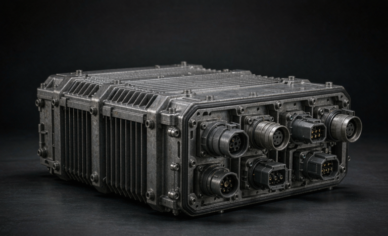
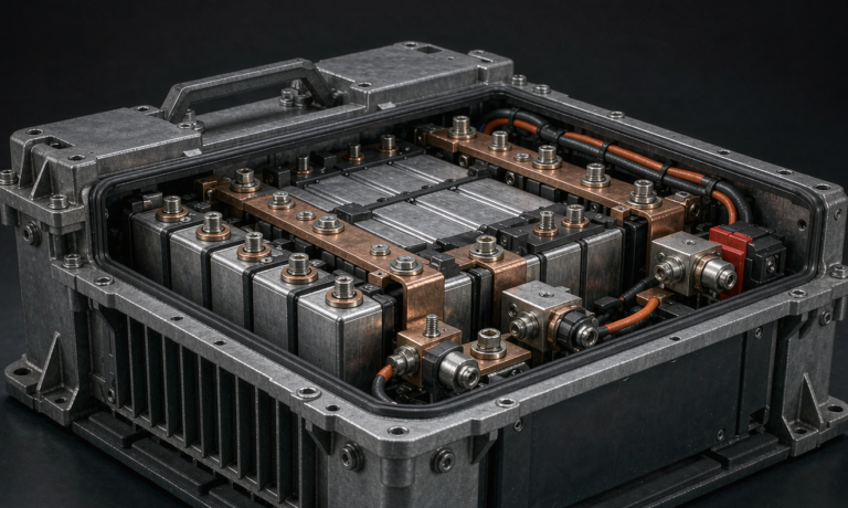
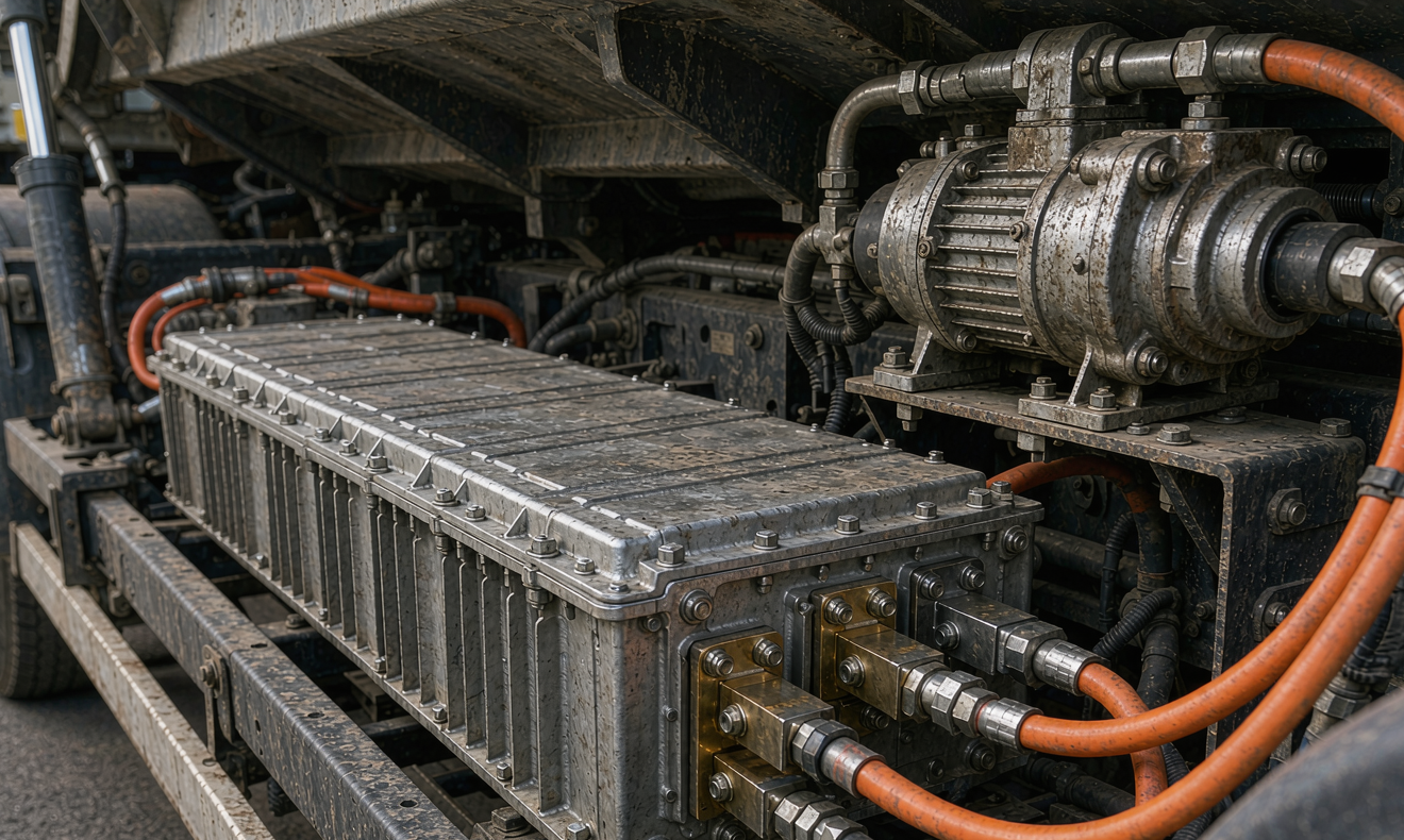
The underbody bay of a refuse truck is a hostile place for a battery. It sees road splash, salt brine in winter, pressure washing, gravel strike, and sustained vibration from the chassis and the hydraulic pump. Our enclosures are built as structural members: a 6061-T6 aluminium case, a corrosion resistant coating, silicone gasketed lids, and internal shock mounts rated for the vertical load the frame sees when the truck hits a curb.
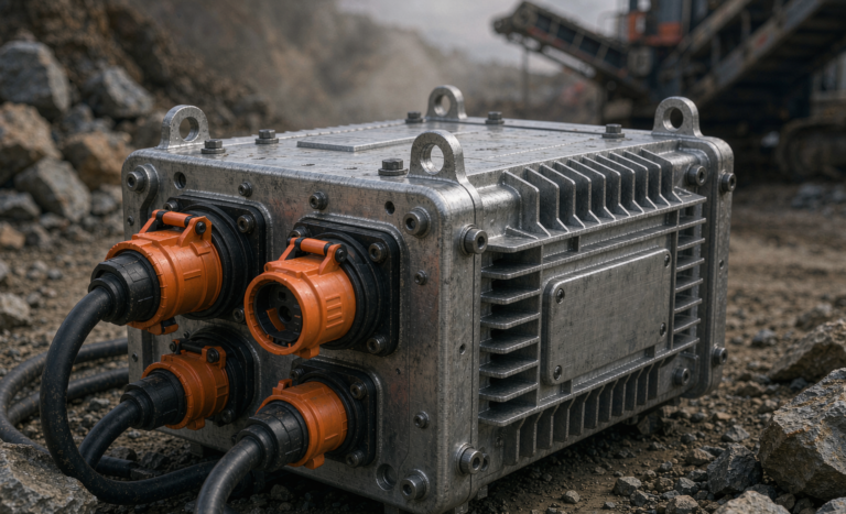
Ingress protection matters more than people expect. We specify IP67 as the floor and IP69K where the body shop pressure washes the chassis, but the connector side is the weak point. Every high voltage connector gets a locked, sealed housing with a service loop, and the copper busbars are nickel plated to survive years of humid coastal air.
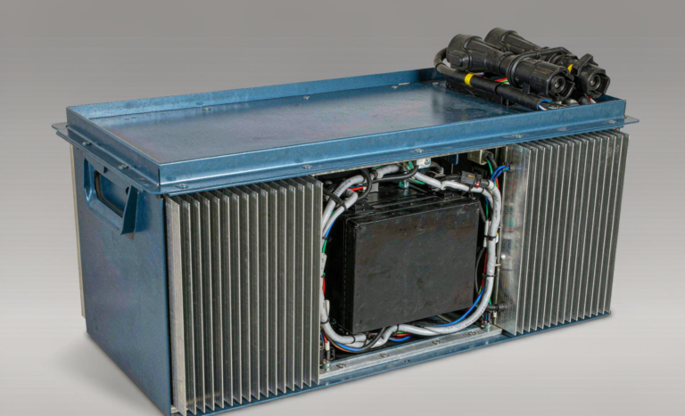
Thermal management is usually liquid. A coolant plate under the module tray carries heat to a low temperature loop that ties into the cab heater, which is a nice packaging win in winter. Our rule of thumb is that we want the cell surface below 45 degrees Celsius at sustained pack power, and below 55 degrees Celsius at peak burst, because every 10 degrees Celsius above 45 roughly halves the calendar life we quote. In hot climates we also derate continuous power by 10 to 15 percent above 40 degrees Celsius ambient rather than let the coolant system grow to a size the underbody bay cannot hold.
Charging Strategy and Depot Infrastructure
Most of our municipal customers charge overnight at the depot, at a modest 0.3 to 0.5 times the pack capacity, over six to eight hours. That is the cheapest electricity, it is easiest to schedule, and it puts very little stress on the cells. The complication is that a refuse route can outlast the overnight window, so a mid shift opportunity charge is common.
An opportunity charge at 150 to 300 kilowatts for ten to fifteen minutes at a transfer station adds 12 to 20 percent state of charge, which is usually enough to finish the route. The engineering caution is lithium plating. Charging a cold pack, below 5 degrees Celsius, at high current deposits metallic lithium on the anode and destroys the cell from the inside. Our chargers refuse the current when the coldest cell in the pack is too low, and the depot management system warms the pack with the coolant loop before the session begins.
We specify the depot side the same way we specify the pack. The charger communicates over CAN bus, the pack reports state of charge, state of health and worst cell temperature, and the depot software stops the session before the state of charge ceiling rather than after. Every pack in the fleet reports the same telemetry to the same dashboard, which is how a fleet manager spots a bad charger or a drifting cell before a route is missed.
Total Cost of Ownership and the Custom Battery Solution
For a fleet director the question is never the sticker price of the pack. It is the cost per kilowatt hour delivered over eight years, and that changes completely when you model the duty cycle. LFP costs less per kilowatt hour and survives the deep daily cycling a refuse route demands, so it wins on operating cost in this application even though NMC carries more energy per kilogram for the same chassis weight.
The rest of the value sits in standardization. When every truck in the depot runs the same pack, the spare pack pool is one pack, the swap procedure is one procedure, and the training is one session. When we build a custom battery solution for a refuse program we freeze the mechanical interface, the connector, the coolant ports and the BMS communication profile so a replacement pack can be swapped in under an hour without a vehicle rework.
Certification is the last gate, and it is not optional for a truck that leaves the country. Cells and packs ship under UN38.3 test conditions, the pack design follows IEC 62133-2 for lithium cells used in portable and vehicular applications, traction packs are evaluated to ECE R100.02, and our own internal acceptance includes a vibration and mechanical shock sequence to ISO 16750-3 plus an external fire and thermal propagation test. Without those documents a customs clearance will stop the truck before the first route.
Frequently Asked Questions
How long do battery packs last in electric refuse trucks?
We warrant a municipal refuse pack for eight years or 1500 full depth equivalent cycles, whichever comes first. In fleet practice the packs hold above 80 percent capacity at the end of that window, because the route duty rarely pushes them past 80 percent depth of discharge every single day.
Can refuse trucks use opportunity charging during collection?
Yes, and many transfer stations do. A 150 to 300 kilowatt session for ten to fifteen minutes at the depot or the transfer point adds enough energy to finish the route. The charger must manage cell temperature to avoid plating, and the pack needs a warm up window in cold climates.
Which chemistry is best for an electric refuse truck battery solution?
Lithium iron phosphate is the default for refuse work. The duty is deep daily cycling with predictable peaks, so cycle life and cost per kilowatt hour matter more than grammes of saved mass, which is exactly where LFP leads.
How much does a battery pack cost for an electric refuse truck?
Traction packs for a 12 to 15 tonne chassis land in a broad band once you include the enclosure, coolant hardware, BMS and certification. The number that matters to a fleet is the cost per delivered kilowatt hour over the service life, which drops sharply when the pack is standardized across the fleet.
Are refuse truck batteries safe mounted under the chassis?
They are, provided the enclosure is sealed, shock mounted and thermally managed, and provided the pack is positioned away from the crush zone of the compaction body. Our packs pass thermal propagation testing so a single cell event does not become a vehicle fire, plus vibration and ingress qualification before release.
What documents do I need to import refuse truck battery packs?
The pack needs UN38.3 test summary and certificates, IEC 62133-2 cell and pack reports, and for vehicular installation ECE R100.02 evaluation. We also provide a technical dossier with the BMS communication map, the cooling loop drawing and the wiring harness schematic so the vehicle integrator can complete the type approval.
Further Reading
References