Battery Solution Reliability for Robotics: An Engineer’s
Reliability is the only specification that matters after the purchase order is signed. I am Karl Huang, Senior lithium battery Engineer at Horizon Power, and over the past decade I have signed off on packs for autonomous mobile robots (AMRs) in cold-storage warehouses, inspection robots crawling through substations, agricultural rovers, and service robots that dock and charge unattended forty times a day. When a robotics program fails in the field, the root cause is almost never raw energy density. It is a mechanical joint that fatigued, a connector that fretted, a thermistor that drifted, or a state-of-charge estimate that wandered until the fleet manager stopped trusting the runtime number on the dashboard. A robust battery solution reliability strategy for robotics is therefore built on test evidence, not datasheets.
This guide is the practical version of the reliability plan we hand to robotics OEMs: what actually breaks, which standards to design against, how we qualify a pack before volume production, and the field data you should be collecting from day one. If you are comparing suppliers, the questions at the end of each section are the ones that separate an engineered battery solution from a re-labelled generic pack.
Why Robotics Packs Fail: Ten Years of Root-Cause Data
Across the returned units I have personally torn down, roughly three quarters of failures fall into four buckets, and none of them are cell chemistry surprises:
- Mechanical and interconnect fatigue (~35%). Ultrasonic-welded nickel tabs, spot-welded busbars, and crimped wire harnesses see continuous 5–200 Hz vibration on hard warehouse floors and door thresholds. Fatigue cracks raise contact resistance, which raises local temperature, which accelerates the crack. It is a self-reinforcing loop.
- Connector wear and fretting corrosion (~20%). A docking robot mates its charge contacts thousands of times per year. Blade and pogo contacts rated for 5,000 cycles are marginal for a robot that docks 40 times a day — that is 14,600 cycles per year.
- Thermal and cycle-life degradation (~20%). Fast opportunity charging at 1C to 2C at a pack temperature of 40–45 °C can double the capacity fade rate compared with charging the same cells at 25 °C.
- BMS firmware, sensing, and communication issues (~15%). SOC drift, CAN bus timeouts, false over-temperature trips from a poorly bonded NTC, and inconsistent behaviour after deep-discharge storage.
The remaining share is genuine cell-level variation and, occasionally, abuse: a forklift strike, a coolant leak, or a customer charging a pack outside its rated window. Note the implication — most reliability work is pack engineering and validation work. That is why our battery pack design reviews spend more time on joints, potting, strain relief, and sensor placement than on selecting a cell.
Define Reliability in Numbers Before You Design Anything
“Reliable” is not a requirement. A reliability specification for a robotics battery application solution needs quantified targets that a test plan can prove or disprove. This is the table we fill in with every customer during the first technical review:
- Duty profile: average and peak current (e.g. 12 A continuous, 45 A for 3 s during lift or hill start), cycles per day, depth of discharge, idle and storage periods.
- Calendar and cycle life target: for example, ≥2,000 cycles to 80% of initial capacity at 25 °C and 1C/1C, plus 5-year calendar life at an average 30 °C ambient.
- Environmental envelope: discharge −20 °C to +55 °C, charge 0 °C to +45 °C, and ingress protection to IEC 60529 IP54 or IP65 depending on whether the robot is washed down.
- Vibration and shock: the profile the robot actually sees, verified with an accelerometer on the pack mounting bracket — not a generic assumption.
- Availability and MTBF: fleet uptime target (e.g. 99.5% of scheduled shifts) and an allowable field return rate, typically <0.5% per year for a mature program.
- Functional safety expectations: which faults must trigger a hard contactor open, which trigger a derate, and what the robot’s supervisory controller must do in each case.
Without these numbers, any supplier can claim compliance. With them, both parties can agree on a pass/fail test matrix — and that is the real deliverable of a serious custom battery solution.
The Standards That Actually Govern Robotics Packs
Robotics sits in an awkward gap: it is not automotive, not consumer electronics, and not aviation. In practice we build to a stack of standards, and I recommend writing all of them into the purchase specification:
- UN 38.3 (UN Manual of Tests and Criteria, Part III, sub-section 38.3) — mandatory for shipping lithium cells and packs. Tests T.1 altitude simulation (11.6 kPa, 6 h), T.2 thermal cycling (−40 °C to +72 °C), T.3 vibration (7 Hz–200 Hz sine sweep, 3 axes, 12 cycles of 15 min), T.4 shock, T.5 external short circuit, T.6 impact/crush, T.7 overcharge, T.8 forced discharge. No UN 38.3 report, no legal air or sea freight.
- IEC 62133-2:2017 — safety of portable sealed secondary lithium cells and batteries, the baseline for most industrial mobile equipment.
- IEC 62619 — safety requirements for secondary lithium cells and batteries for industrial applications, including thermal-propagation and internal short-circuit considerations. This is the one most robotics buyers forget to request.
- IEC 60068-2-6 (sine vibration) and IEC 60068-2-27 (mechanical shock) — for tailoring an environmental test profile beyond the shipping-oriented UN 38.3 sweep.
- IEC 61508 / ISO 13849 — where the pack’s protection functions form part of the robot’s safety function chain; the achievable performance level depends on the BMS architecture and diagnostic coverage.
- FAA and EASA lithium battery rules — relevant if the robot or its spare packs travel by air, and directly relevant to our drone customers. As a rule of thumb, spare packs above 100 Wh require operator approval, and above 160 Wh they generally cannot go as passenger baggage at all. Whenever a robotics customer also flies a drone battery in the same program, we align both packs to the same documentation set to simplify logistics.
Standards prove a pack is not dangerous. They do not prove it will survive 2,000 cycles in your robot. That is what the qualification plan below is for.
Our Qualification Test Plan: From Cell Lot to Fleet Release
We run robotics qualification in four gates. Each gate has an exit criterion, and we do not release tooling or firmware until the gate closes.
Gate 1 — Cell selection and incoming lot control
We characterise at least 30 cells from the production lot: capacity at 0.2C and 1C, DC internal resistance at 10 s / 50% SOC, self-discharge over 28 days at 25 °C and 45 °C, and low-temperature discharge at −10 °C. Our matching window for a robotics pack is ±1.5% capacity and ±5% DCIR within a series string; loose matching is the cheapest way to lose 15% of cycle life. Every incoming lot is sampled again, because “same part number” does not mean “same electrode coating batch”.
Gate 2 — Mechanical and thermal integrity
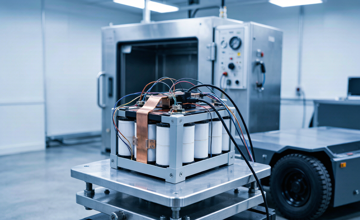
Random and sine vibration per the measured robot profile, typically 8 hours per axis, followed by 3-axis half-sine shock at 30 g / 11 ms. We measure DCIR and cell voltage delta before and after; a resistance rise above 10% on any joint is a fail. Then thermal cycling (−20 °C to +60 °C, 20 cycles, 1 h dwell), IP54 or IP65 ingress verification, and a 1 m drop test on the packaged pack. Every pack is X-rayed or CT-sampled at pilot stage to confirm weld penetration.
Gate 3 — Electrical life and abuse
Cycle life on at least 6 packs using the customer’s real duty profile — not a lazy 1C/1C square wave — with periodic reference capacity checks every 50 cycles at 25 °C. In parallel we run calendar ageing at 45 °C and 60% SOC. Abuse testing covers external short circuit, overcharge, over-discharge, reverse polarity on the charge port, and a single-cell thermal-propagation trigger on the final mechanical configuration. Our acceptance line is 80% capacity retention at the contracted cycle count with no venting, no fire, and no case deformation in abuse tests.
Gate 4 — System integration and firmware soak
The pack runs in the actual robot, on the actual dock, for a minimum 30-day soak: full charge/discharge cycles, sleep and wake transitions, CAN or RS485 communication logging, deliberate connector unplug events under load, and firmware update during a partial state of charge. We look for SOC drift greater than 5% between calibration points, watchdog resets, and any state machine that latches into a fault the operator cannot clear without a tool.
Reliability by Design: The Engineering Details That Decide Field Life
Once the test plan exists, reliability is won in details. These are the items on our internal design review checklist that most often need correction on a first-pass customer design:
- Interconnect strategy. Laser welding for high-current nickel or copper joints, with pull-test sampling at 1 in 200 joints and a documented minimum pull force. Where crimping is unavoidable, we specify the crimp tool, die, and a monthly pull-test log.
- Cell restraint. Cells must be held so that no relative motion is possible between cell and busbar. Foam or silicone potting alone is not restraint; we use compression trays and adhesive with a specified shear strength across the operating temperature range.
- Strain relief. Every wire leaving a PCB is mechanically anchored within 25 mm; vibration works on solder joints, not cable ties.
- Thermal path. A 2 °C spread between cells is normal; above 5 °C the coolest cells become the capacity limiter as the pack ages. We validate the gradient with at least four NTCs at the hottest and coldest predicted positions, bonded with thermally conductive adhesive, never just taped.
- Charge port and docking contacts. For high-cycle docking we specify gold-plated contacts with a wear rating of at least 50,000 mating cycles, plus a pre-charge and soft-start sequence so the contactor never makes or breaks under full inrush.
- Derating strategy in the BMS solution. A good BMS solution does not simply cut off. It derates charge current below 5 °C, tapers discharge above 55 °C, applies dynamic power limits based on measured DCIR, and reports both a hard fault and a soft-warning channel to the robot controller so the fleet can schedule maintenance instead of stranding a unit mid-aisle.
- Serviceability. Modular sub-packs, documented torque values, and a diagnostic port that a field technician can read without disassembly. Reliability includes recovering quickly from the failures that do occur.
Chemistry choice matters too, and it should follow the duty cycle rather than a marketing preference. For indoor AMRs cycling deeply once or twice a shift, LFP gives us 3,000–6,000 cycles and a far more forgiving thermal-abuse profile. For weight-sensitive legged or aerial platforms, high-nickel NMC buys energy density at the cost of tighter thermal management — the same trade-off we manage in every high-performance lithium battery pack we build.
Measuring Reliability in the Field: Data, Not Anecdotes
A pack that passes qualification can still disappoint if nobody watches the fleet. We ask robotics customers to log, at minimum, per-pack cumulative amp-hours, maximum cell temperature per cycle, maximum cell voltage delta at end of charge, DCIR estimate at a fixed reference point, and every fault code with a timestamp. Three derived indicators predict almost every failure we later see on the bench:
- Cell voltage delta growth. A string that ends charge with 15 mV spread in month one and 60 mV in month nine has a weak cell or a degrading joint. Flag at 50 mV, investigate at 80 mV.
- Resistance rise trend. A 20% DCIR rise typically precedes noticeable runtime complaints by several weeks — ideal lead time for planned replacement.
- Temperature excursion count. The number of cycles spent above 45 °C correlates more strongly with capacity fade than total cycle count does. Fixing airflow in the dock is often cheaper than replacing packs.
With this data we set warranty terms honestly, plan second-life redeployment for packs that fall below 80% but remain above 60% capacity, and feed the next design revision. Reliability is a loop, not a certificate.
What to Ask a Supplier Before You Commit
These seven questions reveal engineering depth faster than any brochure:
- Can you show a UN 38.3 report and an IEC 62619 report for this pack configuration, not a similar one?
- What vibration profile did you test, for how many hours per axis, and what was the DCIR change?
- How many packs went through cycle life on my duty profile, and can I see the capacity-versus-cycle curves?
- What is your cell matching window, and how is each incoming lot verified?
- How does the BMS derate rather than trip, and what data does it publish over CAN or RS485?
- What is the documented mating-cycle rating of the charge contacts?
- What field data will you help me collect, and how does it feed warranty and revisions?
At Horizon Power we answer all seven in writing before quoting, because a reliability claim without test evidence is just optimism. Whether the platform is a warehouse AMR, an inspection rover, or a heavy-lift aerial system, the discipline is identical: quantify the duty cycle, design the joints and thermal path for it, qualify against real standards, and keep measuring after deployment.
Frequently Asked Questions
How many cycles should a robotics battery pack deliver?
For an LFP-based AMR pack cycling once or twice per shift, we contract 2,000–3,000 cycles to 80% capacity, and well-managed LFP designs reach 4,000–6,000. High-nickel NMC packs chosen for energy density typically deliver 800–1,500 cycles under the same conditions. The single biggest variable is temperature during fast charging: sustained charging above 45 °C can cut achievable cycle life roughly in half.
Is LFP or NMC more reliable for autonomous robots?
LFP is more tolerant: longer cycle life, a higher thermal-runaway onset temperature, and gentler failure behaviour. It costs roughly 20–30% in volumetric energy density and needs careful low-temperature charge management. NMC makes sense when every gram matters, as it does on aerial platforms. We select per duty cycle and per mass budget, then design the thermal system around the choice.
Which certifications are mandatory for a robotics battery pack?
UN 38.3 is mandatory for transport. IEC 62133-2 is the common safety baseline, and IEC 62619 is the appropriate industrial standard for robotics packs. Depending on the destination market and the robot’s certification path you may also need CE marking with the relevant EMC and machinery directives, UL or CB scheme certificates, and local registration. If packs fly, FAA and EASA lithium rules apply to the shipment as well.
How do I stop state-of-charge drift from stranding robots mid-shift?
Drift comes from coulomb counting without recalibration. Require a BMS that fuses coulomb counting with an OCV-based correction at full charge and at a defined rest condition, that adapts capacity as the pack ages, and that exposes both a raw and a compensated runtime estimate. In our soak tests we treat more than 5% drift between calibration points as a fail.
Can a standard off-the-shelf pack work instead of a custom design?
Sometimes, for prototypes and low volumes. The trade-off is that you inherit somebody else’s mechanical envelope, connector rating, and BMS behaviour. Once you are past a few hundred robots, the cost of one field recall usually exceeds the entire non-recurring engineering cost of a purpose-designed pack with the right joints, sensors, and communication interface.
How long does a full robotics battery qualification take?
Design and prototype build takes 4–6 weeks, and mechanical, thermal, and abuse testing runs another 4–8 weeks. Cycle life is the long pole, so we release on accelerated data plus an interim report and keep testing during ramp. Budget 4–6 months from kickoff to volume release.