Battery Solution for Custom Robotic Platforms
When a customer brings us a new autonomous machine, the first thing I tell my team is simple: the robot is only as reliable as the pack that moves it. Over the last nine years as a senior lithium battery engineer at Horizon Power, I have watched too many promising robotic platforms stall in the field because someone bolted in a generic pack that was never matched to the duty cycle. A real battery solution for custom robotic platforms starts long before a cell is welded — it starts with the load profile, the envelope, and the safety case.
Why Off-the-Shelf Packs Fail Custom Robotic Platforms
Most catalog battery packs are built for a generic 0.2C discharge and a benign 20–25 °C environment. A warehouse AMR, an agricultural weeding robot, or a inspection crawler does none of that. Peak currents during acceleration can hit 5–8C for seconds, regen braking dumps current back into the pack, and the chassis may see 55 °C in a sealed enclosure. When the pack is not specified for that reality, you get voltage sag, premature cutoff, and swollen cells within a season.
That is why we treat every robotic engagement as a battery application solution problem, not a procurement problem. The pack has to earn its place in the mechanical, thermal, and control architecture of the machine.
Mapping the Real Power Profile First
Before I approve a single cell, I ask the OEM for the actual current trace, not a spec-sheet average. We log the platform through a full duty cycle and extract three numbers that drive everything else:
- Average draw — sets the energy capacity (Wh) and run-time target.
- Peak current — sets the continuous discharge rating and the DCIR budget; a pack that sags below the controller’s UV cutoff under peak load will brown out the robot.
- Regen share — sets how much charge the BMS must absorb and how we size the absorption path.
For a typical 25 kg service robot we often see a 2.0C average with 6C peaks. That immediately disqualifies low-rate cells and points us toward high-power NMC or a carefully vented LFP build.
Cell Chemistry: Why a Lithium Battery Platform Usually Wins
For mobile robotics the energy-to-weight ratio is almost always the binding constraint, and that is why a lithium battery platform is the default. The two chemistries we deploy most are:
- NMC (LiNiMnCoO₂) — 200–250 Wh/kg, excellent power density, ideal when mass and volume are tight. We use it for aerial-adjacent and lightweight AMRs.
- LFP (LiFePO₄) — 160–180 Wh/kg, flatter voltage curve, superior thermal margin and 2,000–4,000 cycles. We specify LFP when safety certification or duty-cycle life dominates the business case.
Both are built on proven 18650, 21700, or pouch formats. For a slim robotic arm base we reach for pouches; for shock-loaded ground robots we stay with cylindrical 21700 cells because the steel can takes vibration better.
There is also a cost dimension that OEMs feel at volume. NMC cells currently run roughly 20–40% higher per watt-hour than LFP in production quantities, so whenever the mechanical envelope allows we steer the design toward LFP. That protects the customer’s margin without giving up the field life the application actually needs, and it simplifies the safety case with certification bodies.
battery pack design for Tight Mechanical Envelopes
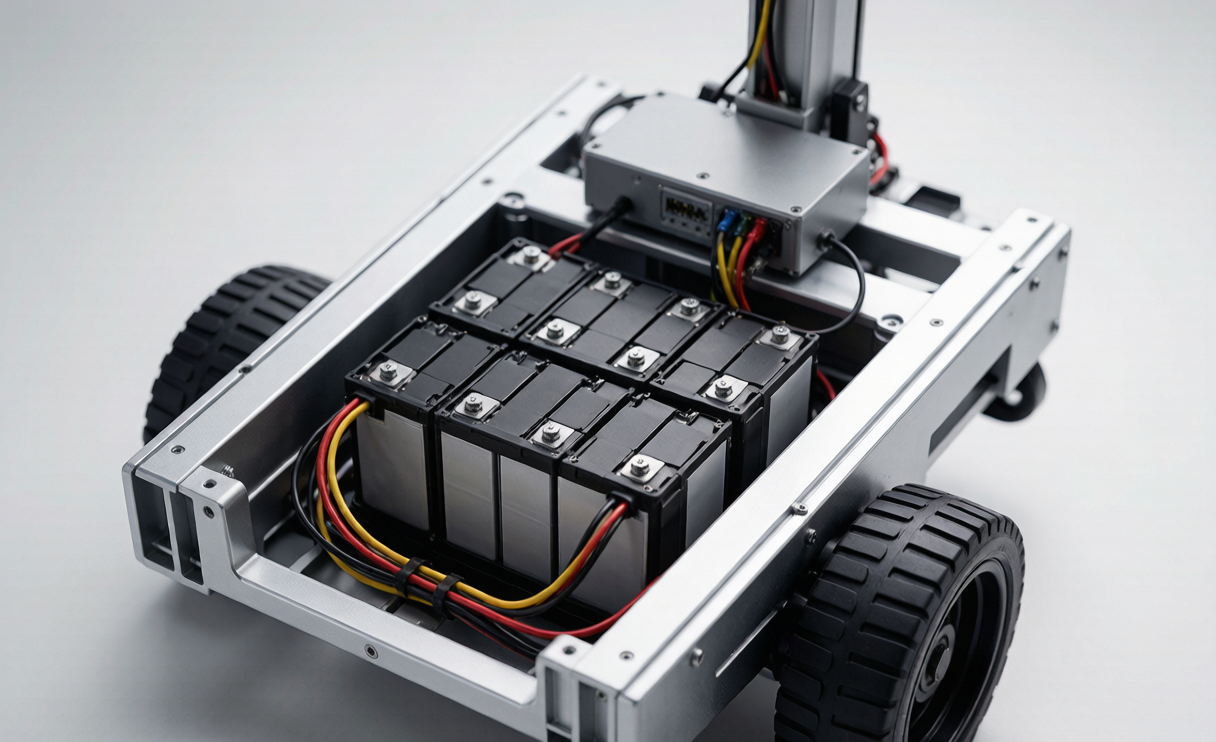
The chassis never has as much room as the electrical team wants. Good battery pack design is therefore a negotiation between energy, cooling, and the mechanical pocket. Our workflow:
- Fix the series count from the motor bus voltage (e.g. 24 V nominal → 7S LFP or 6S–7S NMC).
- Parallel the cells to hit Wh and the peak C-rate without exceeding per-cell limits.
- Reserve 15–20% of the envelope for busbars, sense wiring, and the BMS.
- Seal to the right IP class (we test to IEC 60529; IP54 is common for indoor AMRs, IP67 for outdoor units) and validate against IEC 60068-2-6 vibration and 2-27 shock.
We laser-weld nickel strips rather than solder near cells — soldering heats the can and accelerates aging. The result is a pack that fits the pocket and survives the machine’s lifetime.
The BMS Solution That Keeps a Robotic Fleet Alive
A robot is a fleet asset, not a toy, so the protection electronics matter as much as the cells. Our standard BMS solution covers the full protection set — over-voltage, under-voltage, over-current, short-circuit, and over-temperature — plus the fleet features OEMs actually call for:
- Top-balanced cell balancing to hold pack health across 1,000+ cycles.
- SOH reporting over CAN bus so the depot pulls a pack before it strands a unit.
- Controlled regen absorption so braking energy never pushes a cell past 4.20 V (NMC) or 3.65 V (LFP).
- Pre-charge circuit to protect the robot’s main contactor from inrush.
For swappable packs we add an authenticated coupler so a wrong-chemistry pack physically cannot seat. That single feature has saved more than one customer from a field disaster.
Thermal and Safety Engineering for Mobile Robots
Heat is the silent killer of robotic batteries. We model the pack under the worst-case duty cycle, then add margin. LFP gives us a wide thermal-runaway window, which is why we default to it for anything that shares a space with people. We design vent paths so a single cell fault vents away from the controller, and we keep the pack away from the motor’s hot side.
Every pack ships with a thermal map and a derating curve: above 45 °C we trim the max C-rate; below 0 °C we limit charge current to protect the anode. The robot’s firmware reads that curve from the BMS, so safety is enforced in software and hardware at once.
Cold environments deserve their own design rule. Below 0 °C a lithium cell must not be fast-charged, or metallic lithium plates on the anode and permanently loses capacity. For robots that live in refrigerated warehouses or outdoor winter sites we add pad heaters gated by the BMS and a charge-permit signal, so the pack warms to a safe window before the charger engages. It is a small addition that prevents a whole class of winter failures.
Certification Roadmap: UN38.3, IEC 62133-2, and Air Transport
None of this ships without the paperwork, and buyers in the EU and US ask for it by name. Our certification plan for a robotic battery solution runs through:
- UN38.3 — T.1 altitude, T.2 thermal, T.3 vibration, T.4 shock, T.5 external short, T.6 impact, T.7 overcharge, T.8 forced discharge. This is the baseline for any lithium cell moving by air, road, or sea.
- IEC 62133-2 — the safety standard for secondary lithium cells and batteries, covering cell-level abuse and pack construction.
- IEC 62619 — for industrial stationary and motive packs, which covers most professional robots.
- FAA / EASA air transport — we brief OEMs that loose cells and spares under 100 Wh travel as carry-on, packs 100–160 Wh need operator approval, and anything above 160 Wh moves as cargo under Class 9. A robot demo at a trade show overseas lives or dies on getting this right.
From Prototype to custom battery solution: Our DFM Workflow
We do not hand over a one-off. The path from first article to a custom battery solution in volume is:
- Load-profile capture and chemistry decision (weeks 1–2).
- 3D pack layout and thermal model (week 3).
- EPA prototype, cycled to failure to confirm the model (weeks 4–6).
- Certification build and UN38.3 / IEC testing (weeks 7–10).
- DFM release: weld fixtures, test jigs, and a traceable BOM so every pack off the line matches the certified one.
By the time a customer reaches volume, the pack has already survived the abuse the field will throw at it. That is the difference between a battery that ships and a battery application solution that stays in service.
Frequently Asked Questions
What battery chemistry is best for a custom robotic platform?
It depends on the constraint. If mass and volume are tight and peak power is high, NMC (200–250 Wh/kg) wins. If safety certification, cycle life, and a wide thermal margin matter most, LFP (160–180 Wh/kg, 2,000–4,000 cycles) is the better battery solution. We decide from the logged load profile, not a catalog.
How long does a custom robotic battery pack last?
A well-specified LFP pack in an AMR typically delivers 2,000–3,000 full cycles before it drops to 80% capacity; NMC runs 800–1,500 cycles. Run-time per charge depends on capacity and average draw, but most service robots we build run 4–8 hours on a single pack.
Can the pack be certified for air transport to a trade show?
Yes. We design to UN38.3 and brief the OEM on FAA/EASA rules: under 100 Wh as carry-on, 100–160 Wh with operator approval, above 160 Wh as Class 9 cargo. We supply the test summary the carrier requires.
How do you keep a robotic fleet from stranding itself on a weak pack?
The BMS reports state-of-health over CAN bus, so the depot schedules a pack for swap before it fails. Combined with top balancing and a controlled regen path, this is what turns a battery into a manageable fleet asset.
What information do you need to start a custom battery design?
The current trace across a full duty cycle, the mechanical envelope (a STEP file is ideal), the motor bus voltage, the target run-time, and the certification markets. With those five inputs we can usually return a first battery pack design within three weeks.